
CryoMLI
CryoMLI 201
MLI construction for LN2 and argon applications, piping, cold boxes, and vacuum-jacketed systems.
Typical applicationsVacuum piping
Engineering datasheet
Selection data and declared limitations
Technical sales will review the requested product and application conditions, then reply by email with document availability and next steps.

- Structure
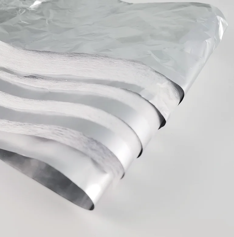
- Aluminum foil + synthetic fiber
- Temperature range
- 4 K-423 K
- Recommended vacuum condition
- For a qualified evacuated insulation space. Final pressure, pump-down method, residual-gas load, hold time, and vacuum-maintenance strategy must be defined for the installed assembly; performance degrades as gas conduction increases.
- Thermal performance
- Apparent thermal conductivity and heat flux are installed-system values, not unconditional roll-material properties. No single value is published here. Request data for stated hot / cold boundary temperatures, vacuum level, layer density, seam design, and test method.
- Width and roll options
- Master-roll availability plus custom slitting and rewinding are confirmed by RFQ. Specify finished width, width tolerance, roll length, core, winding direction, and packaging limits.
- Layer configuration options
- Available as constituent reflector / spacer materials or as project-specific multilayer packages. Layer count and installed density are selected from boundary temperatures, vacuum, geometry, and target heat leak.
- Processing options
- Slitting and rewinding to confirmed dimensions
- Sewing and blanket assembly where the structure permits
- Drawing-based or sample-based cutting
- CNC vibration-knife profile cutting, openings, and project kit packaging
- Typical applications
- Notes and limitations
- Not a structural support, pressure boundary, seal, or substitute for vacuum-system design.
- Published temperature ranges describe constituent material capability; adhesive, seam, contamination, oxygen-service, and installation limits can narrow the usable range.
- System heat leak must be validated for the actual assembly and test conditions.
- Download PDF
Product technical table
CryoMLI 201 technical data
The table below is published as product-level reference data. Final use still depends on application geometry, vacuum condition, installation density, cleanliness, and customer validation.
| Item | Unit | Technical specification |
|---|---|---|
| Synthetic Fiber basis weight | g/m² | 15 ±1 |
| Synthetic Fiber thickness | mm | 0.08 ±0.01 |
| Synthetic Fiber thermal conductivity | W/(m·K) | < 0.032 |
| Synthetic Fiber moisture content | % | < 10 |
| Synthetic Fiber loss on ignition | % | < 0.3 |
| Aluminum foil basis weight | g/m² | 17 ±1 |
| Aluminum foil thickness | mm | 0.0065 |
| Aluminum foil emissivity | ε | 0.028 (@87K, NASA GRC) |
| Thermal shrinkage rate (180°C, 30min) | % | ≤ 3.0 |
| Spacer Gas Permeability | - | Moderate (fiber mat, moderate pump-down) |
| Comprehensive tensile strength | MPa | ≥ 190 |
| Apparent thermal conductivity | W/(m·K) | < 1.22×10 -4 |
| Leak outgassing rate | Pa·m³/(s·g) | < 2.8×10 -7 |
| Reference Heat Flux (20 layers, 78K-293K) | W/m² | ~1.0 (est., ref: NASA C116, foil + polyester fabric) |
| Operating Vacuum Requirement | - | < 1×10 -4 Torr (high vacuum) for rated performance |
| Appearance | - | Smooth surface, free of impurities |
| Standard Widths | mm | 90 / 100 / 200 / 300 / 910 / 1310 / 1800 |
| Maximum Production Width | mm | 1800 |
| Custom Width | - | Available (MOQ and surcharge apply) |
| Composite Layer Configurations | - | 5/5, 10/10, 20/20 (mature); custom available |
| Recommended Layer Density | layers/mm | 1.0 - 2.0 |
| Roll Material — Max Layers | - | Up to 10/10 |
| Shape Customization | - | Supported (vibration knife cutting) |
| Processing Capabilities | - | Rewinding, sewing, cutting, lamination |
| Production Method | - | Fully automated mechanical production |
| Application Temperature Range | - | 4K(-269°C) - 423K(150°C) |