Application material system
Aerospace & Rocket Thermal Control
Integrate lightweight insulation and fixing materials around vehicle geometry, vibration loads, thermal cycling, cleanliness constraints, and installation interfaces.
East Far material scope
Relevant East Far products
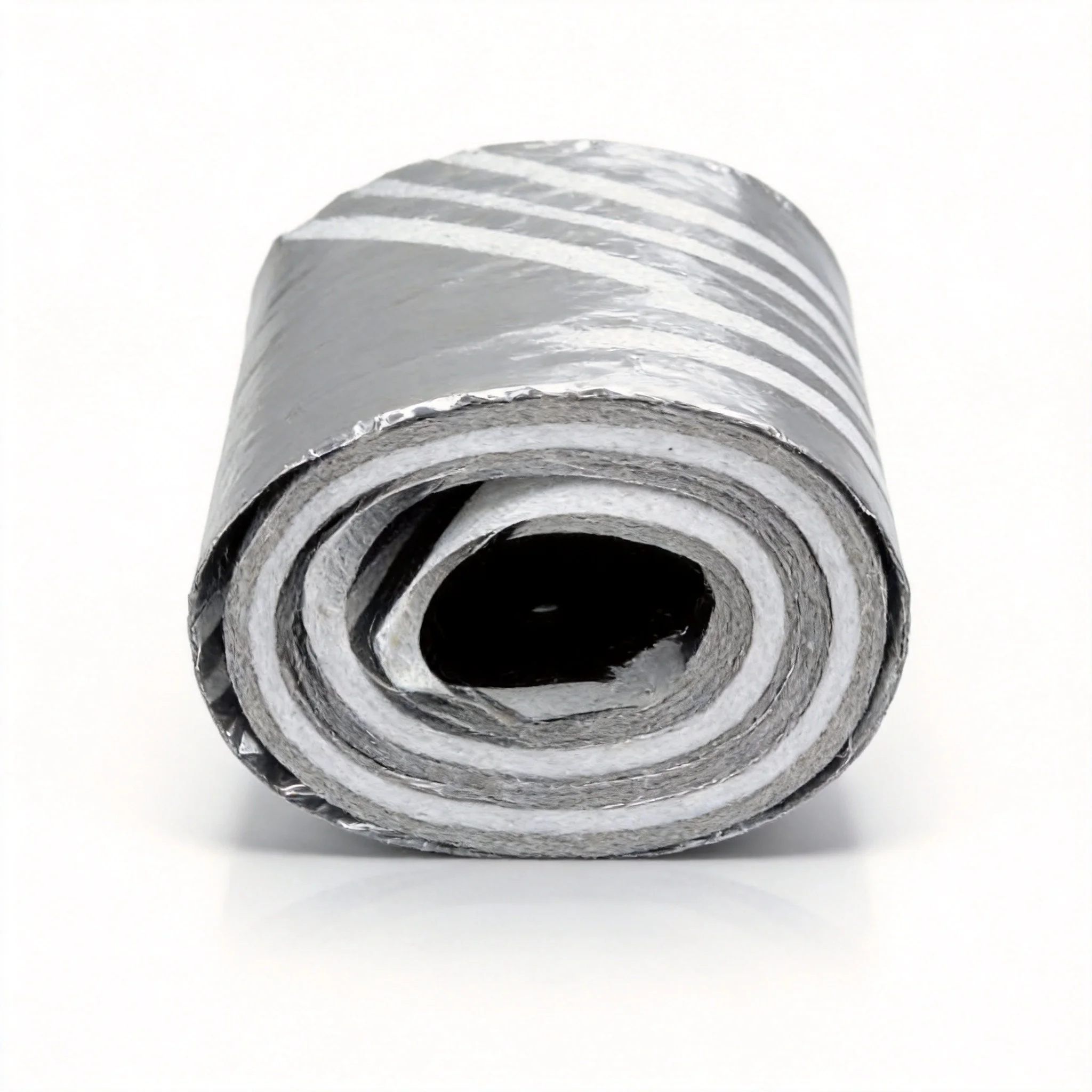
CryoFilm Al-PET / Al-PI
Reflective film material for cryogenic MLI layers, venting layers, spacecraft-style thermal blankets, and drawing-based insulation kits.
CryoMLI 102
Low-emissivity MLI for cryogenic storage, transfer, spacecraft thermal control, and superconducting systems.
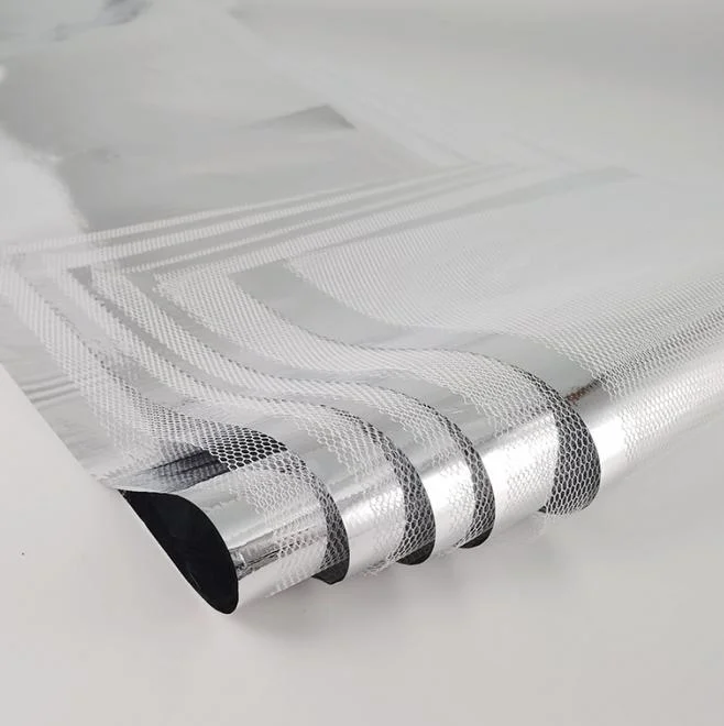
CryoMLI 302
Open spacer structure for high-vacuum cryogenic systems, superconducting systems, and spacecraft MLI blankets.
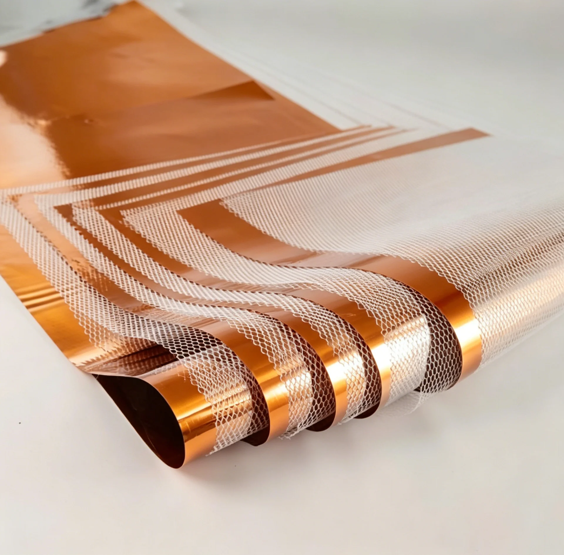
CryoMLI VDMix
Custom variable-density MLI package for LH2, fusion, accelerator, and research cryogenic systems.
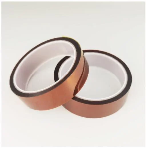
CryoTape PI
High-temperature and cryogenic-compatible tape for aerospace, superconducting, and research systems after project review.
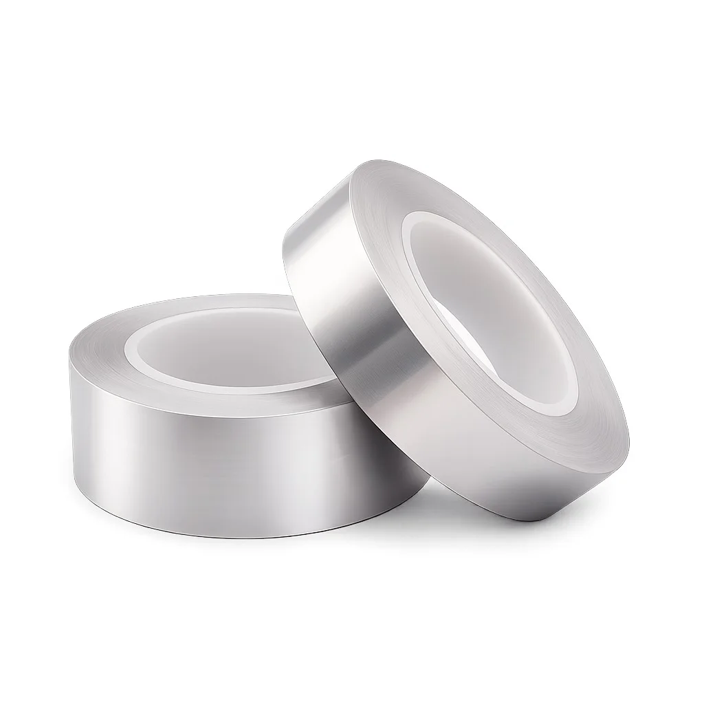
CryoTape MAP
Strong-adhesion cryogenic tape for LNG and LH2 material packages, MLI fixing, and external thermal-protection assemblies.
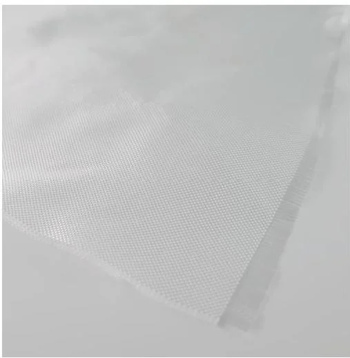
CryoFiG Fabric
Outer protection and reinforcement fabric for cryogenic material packages.
Engineering scope
Key engineering challenges
- Limit mass while controlling radiative heat transfer
- Accommodate vibration, thermal cycling, and complex cut-outs
- Define outgassing, flammability, and contamination requirements before selection
System layers
- 01 Vehicle interface
Tank, line, shield, or structure with project-defined bonding and cleanliness controls.
- 02 Thermal-control insulation
CryoMLI reflective / spacer package cut to geometry and thermal-zone requirements.
- 03 Localized fixing
CryoTape PI or MAP considered at seams and interfaces after mission-specific qualification.
- 04 External protection
Project-selected reinforcement or protective layer, including CryoFiG where its construction is suitable.
Supporting materials and supply boundaries
East Far Cryo supplies cryogenic insulation materials, related processing, and material-selection support. Equipment and system responsibilities remain with the project owner and equipment designer.
- Flight structures, propellant tanks, feed lines, fasteners, sensors, coatings, and launch hardware are outside East Far Cryo's manufacturing scope.
- Flight qualification, flammability, atomic-oxygen, radiation, and contamination acceptance remain mission-owner responsibilities.
- Supplied-material profile cutting can be discussed where the customer owns the material specification.
Parameters needed for quotation
- Cryogenic medium and normal / transient operating temperatures
- Target vacuum level, pump-down method, hold time, and expected residual-gas load
- Equipment geometry, dimensions or surface area, penetrations, and installation access
- Target heat leak or required layer count and any governing acceptance method
- Required delivery form: rolls, slit widths, sewn blankets, profile-cut parts, or installation kits
- Mission environment, load cases, allowable mass, drawing revision, cut-out geometry, and qualification requirements
Downloads and technical contact
CryoMLI Series Product Brochure
Product structures, specifications, and application notes for CryoMLI materials.
CryoTape Series Product Brochure
Cryogenic tape structures, temperature ranges, and fixing recommendations.
MLI Technical Reference
Engineering reference for MLI material selection, vacuum, heat flux, and layer density.