
Perforated Aluminized Film for MLI: Material Selection and Layer Application
Perforated aluminized film is used as a radiation-shield layer in multilayer insulation (MLI). The film is not selected by thickness alone. For liquid hydrogen tanks, vacuum cryogenic equipment, satellite blankets, and cryostats, the final choice depends on substrate material, metallized side, aluminum coating thickness, perforation pattern, spacer contact, venting path, and the layer position inside the blanket.
This guide focuses on PET and PI base films from 6.5 μm to 25 μm, with a nominal 600 Å aluminum layer, and explains how those choices translate into practical MLI layer design.
What The Film Does In An MLI Stack
An MLI blanket works by splitting one large radiation exchange into many smaller radiation exchanges. Each aluminized film layer acts as a low-emittance shield. Spacer materials or crinkled film reduce solid contact between shields, while the vacuum suppresses gas conduction.
In real cryogenic hardware, the layer is also a manufactured part. It must survive winding, cutting, stitching, handling, pump-down, venting, installation, and thermal cycling. A technically correct film that cannot be repeatably cut, labeled, vented, or installed is not a good MLI layer.
Base Film Thickness: 6.5 μm To 25 μm
Thin substrates reduce mass and reduce conductive heat leak through the film edge and contact points, but they are harder to handle. Thicker substrates improve handling, flatness, and tear resistance, but add solid conduction paths and blanket stiffness.
| Base film thickness | Approx. imperial thickness | Typical engineering role |
|---|---|---|
| 6.5 μm | 0.26 mil | Lightweight inner radiation shields where low mass and low solid conduction are priorities |
| 12 μm | 0.47 mil | General MLI radiation layers with a balance of handling and thermal performance |
| 25 μm | 0.98 mil | Outer layers, tooling-sensitive cuts, reinforcement positions, or blankets needing higher handling strength |
For high-performance vacuum MLI, thinner is not automatically better. If a 6.5 μm film wrinkles, bridges, tears, or creates uncontrolled contact points during assembly, the installed blanket may perform worse than a slightly thicker, more stable layer.
PET Versus PI Substrate
PET aluminized film is widely used where cost, roll processing, dimensional consistency, and general cryogenic insulation performance matter. It is a practical choice for many liquid nitrogen, liquid oxygen, LNG, and liquid hydrogen support applications when the temperature, cleanliness, and mechanical conditions are within the project limits.
PI aluminized film is selected when the environment is more severe. It is commonly considered for spacecraft thermal blankets, higher-temperature exposure, stronger dimensional stability requirements, radiation-sensitive environments, or hardware that must tolerate more demanding bake-out and service conditions.
The practical selection logic is:
| Substrate | Strengths | Tradeoffs |
|---|---|---|
| Aluminized PET | Cost-effective, easy to process, suitable for many cryogenic MLI blankets, good roll availability | Lower high-temperature margin than PI; project temperature and outgassing requirements must be checked |
| Aluminized PI | Better high-temperature capability, strong dimensional stability, widely used in demanding spacecraft-style MLI systems | Higher cost, different handling stiffness, and project-specific procurement requirements |
NASA outgassing evaluation is usually discussed through ASTM E595 data, including TML and CVCM. For space or high-vacuum cryogenic use, the substrate, coating, adhesive tapes, edge closures, labels, and any thread or spacer must be evaluated as a system, not as isolated film sheets.
Aluminum Coating Thickness: 600 Å
A 600 Å aluminum coating is about 60 nm, or about 2.36 microinch. At this scale, the coating provides a reflective, low-emittance metallic surface without turning the film into a structural metal foil.
For MLI design, 600 Å should be treated as a controlled optical and surface specification:
- It supports low-emittance radiation shielding.
- It keeps the layer flexible and roll-processable.
- It should be specified with side, coverage, surface resistance or optical criteria when the project needs traceability.
- It does not remove the need to control spacer contact, layer density, edge compression, and venting.
Single-Side Versus Double-Side Aluminized Film
Single-side aluminized film has one metallized surface and one polymer surface. It can be enough when only one dominant radiative exchange side needs to be controlled, or where cost and simpler construction are important.
Double-side aluminized film gives both faces a low-emittance surface. It is often preferred for internal MLI radiation shields, where each layer sees neighboring layers on both sides. It can improve radiative symmetry, reduce dependence on layer orientation, and simplify installation rules.
The tradeoff is not purely thermal:
| Metallizing format | Best used when | Engineering caution |
|---|---|---|
| Single-side aluminized | Cost, weight, or one-direction radiation control is the main driver | Orientation must be controlled during cutting and installation |
| Double-side aluminized | Internal MLI shields need low-emittance surfaces on both faces | Specify handling protection, electrical behavior, and any ESD or grounding requirements |
For a fabricated kit, the cutting drawing should state whether the aluminized side faces hot side, cold side, or both sides are metallized. This avoids field installation errors.
Perforation Analysis
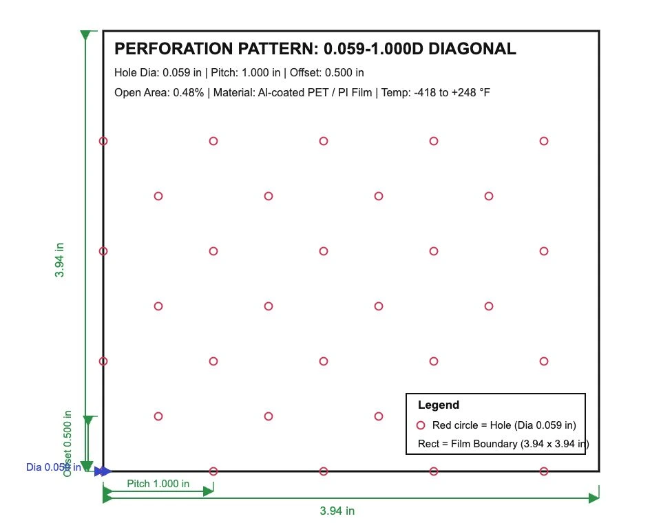
Perforations are mainly used to support vacuum pump-down and trapped-gas venting. They are especially important when layers are large, closely packed, wrapped around cylindrical hardware, or sealed near edges and penetrations.
The example pattern uses:
- Hole diameter: 1.50 mm / 0.059 in
- Pitch: 25.40 mm / 1.000 in
- Offset: 12.70 mm / 0.500 in
- Nominal open area: 0.48%
Open area affects two competing requirements. More open area improves venting and reduces trapped gas pockets during pump-down. Too much open area removes reflective area, increases direct radiation view paths, and can weaken the film around cuts, seams, and fastener zones.
For design review, do not only ask for “perforated film.” Ask for:
- Hole diameter and tolerance
- Pitch and diagonal offset
- Nominal open area and calculation method
- Whether the pattern is centered to the part boundary
- Minimum edge distance around seams, holes, slots, and tabs
- Whether perforations are needed in every layer or only selected venting layers
Application-Layer Selection
In an MLI blanket, not every layer has the same job. A practical material stack can combine different film thicknesses, substrates, and metallized formats.
| Blanket position | Typical layer choice | Reason |
|---|---|---|
| Warm-side outer region | 12 μm or 25 μm aluminized PET or PI | Better handling, cutting stability, and installation durability |
| Internal radiation shields | 6.5 μm or 12 μm double-side aluminized PET or PI | Lower mass and lower solid conduction while keeping both faces reflective |
| Venting-control layers | Perforated aluminized film with controlled pitch and open area | Allows pump-down through the blanket without opening large direct radiation paths |
| Cold-side region | Lower layer density, careful spacer contact, thin low-conduction layers | Cold-side solid conduction and contact effects can become more important in the total heat leak |
| External spacecraft-style blanket | PI-based outer or internal layers when specified | Higher temperature margin and demanding environmental compatibility |
For liquid hydrogen MLI, the cold-side region deserves extra attention. A dense stack near the cold boundary can increase contact and solid conduction. Lower cold-side layer density, clean vent paths, and controlled spacer geometry can be more effective than simply adding more layers.
Recommended RFQ Parameters
When sending a drawing or requesting a material kit, include:
- Cryogen or operating medium
- Hot-side and cold-side temperatures
- Vacuum level and pump-down process
- Film substrate: PET or PI
- Base film thickness: 6.5 μm, 12 μm, 25 μm, or project-specific
- Aluminum coating: 600 Å, single-side or double-side
- Perforation pattern: hole diameter, pitch, offset, and open area
- Blanket layer count and whether perforation applies to all layers
- Part drawings, edge closures, penetrations, labels, and packaging method
East Far Cryo can prepare aluminized film, perforated MLI layers, spacers, tapes, and drawing-based cryogenic insulation kits for vacuum cryogenic systems, liquid hydrogen equipment, cryostats, and spacecraft-style thermal blankets.
Request engineering support or review Cryogenic Material Kits from Engineering Drawings for drawing-based cutting, labeling, and batch packaging.
Technical References
- NASA Goddard Space Flight Center, Outgassing Data for Selecting Spacecraft Materials
- NASA, Outgassing Description and ASTM E595 context
- ESA, Multi-layer insulation blankets
- ESA, Thermal insulation installation on Juice
- ScienceDirect, Multilayer Insulation for Spacecraft Applications